


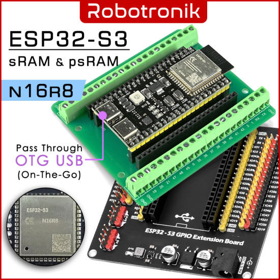


ESP32 S3 Dev Board - 2 x USB-C
The ESP32-S3 development board is assembled with an original ESP32-S3-WROOM-1 module from Espressif, with 16MB Flash and 8MB PSRAM (ESP32-S3-WROOM-1-N16R8). It is a general-purpose Wi-Fi + Bluetooth® LE MCU module that integrates complete Wi-Fi and Bluetooth LE functions. Most of the I/O pins on the module are broken out to the pin headers on both sides of this board for easy interfacing.
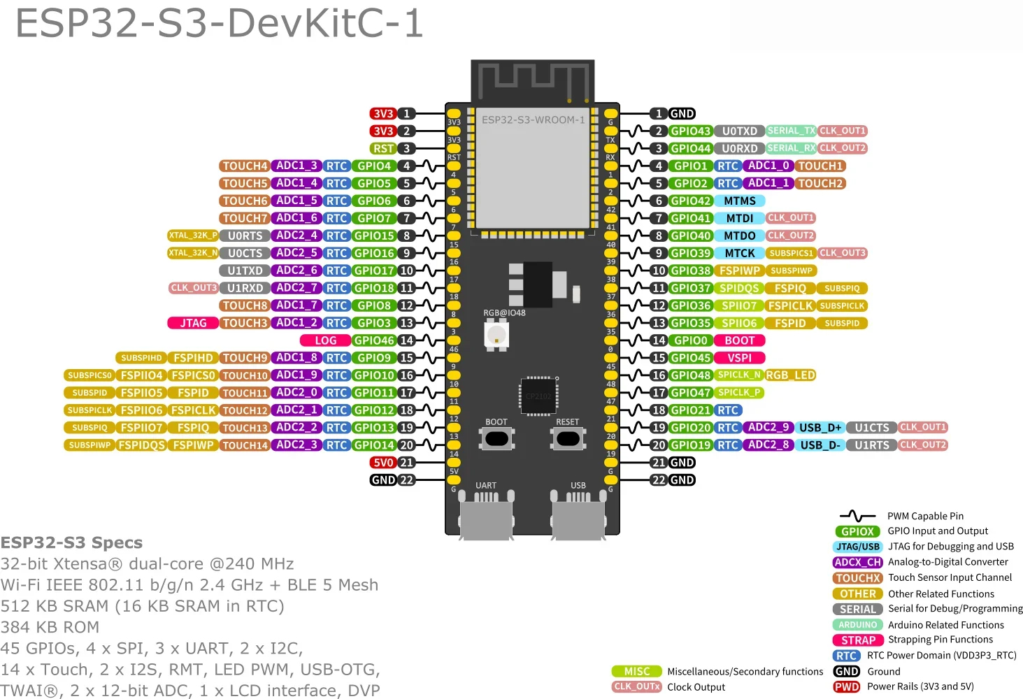
The ESP32-S3 is a dual-core XTensa LX7 MCU, capable of running at 240 MHz. Apart from its 512 KB of internal SRAM, it also comes with integrated 2.4 GHz, 802.11 b/g/n Wi-Fi, and Bluetooth 5 (LE) connectivity that provides long-range support. It has 45 programmable GPIOs and supports a rich set of peripherals. ESP32-S3 supports larger, high-speed octal SPI flash, and PSRAM with configurable data and instruction cache. There is an RGB WS2812 LED connected to IO38. It has a Red, Green, and Blue LED that are individually addressable. This module has 2 USB Type C connectors. The one is used to power the board, flash applications to the chip, and communicate with the chip via the onboard USB-to-UART bridge. It is connected to a UART of the ESP32 chip via a CH340 chip. The second USB connector is connected to the ESP32-S3 full-speed USB OTG interface, compliant with the USB 1.1 specification. It can also be used to power to the board, for flashing applications to the chip, for communication with the chip using USB 1.1 protocols, and for JTAG debugging.
Quick Spec
- Dual-core 32-bit LX7 CPU, frequency up to 240MHz
- 2.4 GHz Wi-Fi, EEE 802.11 b/g/n-compliant
- Bluetooth, LE: Bluetooth 5, Bluetooth mesh
- SPI Flash
- N16R8: 16 MB (64Mbit)
- N8R2: 8 MB (32Mbit)
- 384 KB ROM
- 512 KB SRAM
- SPI PSRAM
- N16R8: 8 MB
- N8R2: 2 MB
- 16 KB SRAM in RTC
- Communication Interfaces
- 2 x I2C
- 2 x I2S
- 4 x SPI
- 3 x UART
- 1 x USB OTG
- Security
- 4096 bit OTP
- AES, SHA, RSA, ECC and RNG
- Secure boott, Flash encryption, Digital signature, HMAC module
- Dual Type-C USB connectors
- Reset and User/Firmware buttons
- RGB WS2812 User LED
- Power LED
- Virtual USB port provided by CP2102 for debugging and firmware upgrade
- Supply Voltage: 5V via USB
- Circuit Voltage: 3.0 to 3.6V Circuit Operation
Resources
- YD-esp32-s3-devkitc-1-clone-high-resolution-pinout-and-specs
- User Guide
- Schematic
- ESP32-S3-WROOM-1 Datasheet
Basic Arduino IDE v2.X.Y "Tools" menu starting
settings for the AI-S3 ESP32-S3 Dev BoardBoard: "ESP32S3 Dev Module"
Port: [pick_the_board_port]USB CDC On Boot: "Disabled"
CPU Frequency: "240MHz (WiFi)"
Core Debug Level: "None"
USB DFU On Boot: "Disabled"
Erase All Flash Before Sketch Upload: "Disabled"
Events Run On: "Core 1"
Flash Mode: "QI0 80MHz"
Flash Size: "8MB (64Mb)"
JTAG Adapter: "Disabled"
Arduino Runs On: "Core 1"
USB Firmware MSC On Boot: "Disabled"
Partition Scheme: "8M with spiffs (3MB APP/1.5MB SPIFFS)"
PSRAM: "Disabled"
Upload Mode: "UARTO / Hardware CDC"
Upload Speed: "921600"
USB Mode: "Hardware CDC and JAG"
Programmer: "Esptool"
Plug the USB cable in to the "COM" port (right hand port when viewed from the top with USB connectors at the bottom).
Match the Partition Scheme to the board hardware flash size & sketch requirements.
Set PSRAM: to "Enabled" if required in your sketch.
ESP32 S3 w/ SPI PSRAM (N8R2 8M / N16R8 16M) # YD-ESP32-S3 (DevKitC 1 clone)
- Product Code: M-CTRL-ESP32-S3
- Availability: 10086
RM9.99 ~ 50.99
- Ex Tax: RM0.00