


✍Specification :
1. Module size: 20.5MM*41MM
2. Module weight: 54g
✍Main technical parameters of 1602LCD :
1. Display capacity: 16×2 characters
2. Chip working voltage: 4.5—5.5V
3. Working current: 2.0mA (5.0V)
4. The suitable working voltage of the module: 5.0V
5. Character size: 2.95×4.35(W×H)mm
1 VSS power ground 9 D2 data
2 VDD power supply positive 10 D3 data
3 VL liquid crystal display bias 11 D4 data
4 RS catalog/command selection 12 D5 data
5 R/W read/write selection 13 D6 data
6 E enable signal 14 D7 data
7 D0 data 15 BLA backlight positive
8 D1 data 16 BLK backlight negative
✍Pin 1: VSS is the ground power supply.
✍Pin 2: VDD is connected to 5V positive power supply.
✍The third pin: VL is the contrast adjustment terminal of the liquid crystal display, the contrast is weak when connected to the positive power supply, and the contrast when grounded
✍High, when the contrast is too high, it will produce "ghosting". When in use, you can adjust the contrast through a 10K potentiometer.
✍Pin 4: RS is the register selection, the data register is selected at high level, and the instruction register is selected at low level.
✍Pin 5: R/W is the read and write signal line, read operation at high level, and write operation at low level. When RS
✍It can write commands or display address when it is low level together with R/W, when RS is low level and R/W is high level
✍The busy signal can be read, and data can be written when RS is high and R/W is low.
✍Pin 6: End E is the enable end. When end E changes from high level to low level, the LCD module executes the command.
✍Pins 7 to 14: D0 to D7 are 8-bit bidirectional data lines.
✍Pin 15: the positive pole of the backlight.
✍Pin 16: the negative pole of the backlight.
▖▖▖▖▖▖▖▖▖▖▖▖▖▖▖▖▖▖▖▖▖▖▖▖▖▖▖▖▖▖
???? Anything can ws us @ +6018 2870 232 ✅
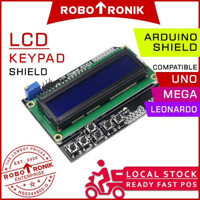
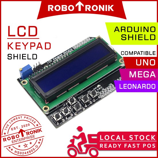
UNO LCD Keypad Shield 16x2 Character Expansion Shield, Arduino UNO Compatible
- Product Code: SHIELD-LCD-KEYPAD
- Availability: Out Of Stock
RM13.99
- Ex Tax: RM13.99